DDR-5 Gallery
The DDR-5 family of receivers could be, and were, configured in a huge
variety of ways. To maintain some semblance of sanity while sorting
through the photos of these receivers, I built the following tables. With
any luck, this may help you sort through the various options... Among the
many TMC documents was a fat binder evidently used by Ernie Matson (VP Sales) to
help configure DDR-5 radios. This included single-page drawings of some of
the configurations, and I've included scans of the ones I have. There are
also a bunch of example system diagrams on large drawings. I'll add them
and a more thorough technical discussion of the remote-tuned Technimatic DDR-5's
at some point.
Manually Tuned DDR-5's
DDR-5 Modules
To figure out which of the many version of this receiver you're dealing with,
you first have to be able to recognize the components of the system. I
found the following table to be useful:
| Module |
Picture |
Function |
| HFR |
 |
RF Tuner. This unit is essentially a
conventional front end with first mixer for a superhet radio. It's
local oscillator includes a varactor that allows it to be phase-locked to
the synthesizer. The unit also includes the first IF amplifier at
1.75Mc. HFR-1 shown. |
| HFS |
 |
Synthesizer. This unit is the synthesizer used
to phase-lock the local oscillator to the operating frequency. It
has a numerical readout, but its digits are merely set by the frequency
switches. HFS-1 shown. |
| AFC |
 |
Automatic Frequency Control. This unit operates
within the 250Kc IF of the receiver and compensates for drift in the
receiver front end, and in the distant transmitter. AFC-2 shown. |
| HSP |
 |
Audio Switch Panel. |
| HFI |
 |
IF Amplifier. Contains the 2nd mixer, 250 Kc IF
amplifier, and set of bandpass filters. HFI-1 shown. |
| HNF |
 |
Variable Notch Filter. This filter sits in the
250Kc IF chain. It up-converts to 447-460Kc, passes through a fixed
notch filter, then down-converts to 250Kc again, using a pair of mixers
and internal 197-213Kc oscillator. HNF-1 shown. |
| HFA |
 |
Detector and Audio Amplifier. Contains an AM
detector, product detector, BFO, and audio output stages. HFA-1
shown. |
| HAF |
 |
Audio Filter. A passive LC dual-channel filter
with independent hi- and lo-pass functions. HAF-1 shown. |
| HFP |
 |
Power Supply. Dual regulated supply that
supplies most of the B+ and filament voltages for the receiver. It
also provides switched AC supply for certain functions. HFP-1 shown. |
| HSS |
 |
Speaker Panel. HSS-1's (one speaker) and HSS-2's (dual
speakers) are used in various configurations. Shown is an LSP-1, since
I don't have a decent photo of an HSS--they're nearly identical. |
| DVM |
 |
Diversity Visual Monitor. Visual tuning aid for
diversity operation. |
| HPP |
 |
Power Panel. |
| MSA |
 |
Multiple Sideband Adapter. This unit contains a
common 3rd mixer that converts the 1.75Mc IF input down to 250Kc.
There are then four independent IF's spaced symmetrically around
250Kc (2 below, 2 above), with independent AGC's and four independent sets
of product detectors, BFOs, squelch, and AF amplifiers. This
unit usually works with MCG. MSA-1 shown. The MSA/MCG pair
essentially replaced the HFI & HFA of the earlier receivers. |
| MFP |
 |
Power Supply. Supplies power to the MSA.
MFP-1 shown. |
| MCG |
 |
Multiple Carrier Generator. Provides the 2Mc
translation frequency for the 3rd mixer, and BFO injections at 243.71,
250.00, and 256.29 Kc for the MSA. MCG-1 shown. |
| SBS |
 |
Multiple Sideband Adapter. This unit contains an input
mixer, a 250Kc IF with multiple filters, and two sets of AM and product
detectors, and 2 audio outputs. |
| HFF |
 |
Radio Frequency Amplifier, Fixed Tuned. This
unit replaces the HFR in the various fixed-tuned receivers, providing 8
pre-set, fixed receive frequencies. |
| |
|
|
Overview
The chart below outlines the various configuration of manually tuned
DDR-5's. Many of these configurations had military designations; refer to
the cross-reference chart to see
which is which.
| Type |
Tuner |
Synthesizer |
AFC |
IF/Audio |
Spkrs |
Pwr Supply |
AC Pnl |
Other |
Dwg |
| DDR-5 |
HFR-1 |
HFS-1 |
AFC-3 |
HFI-1, HFA-1, HSP-1 |
|
HFP-1 |
|
|
|
| DDR-5A |
2xHFR-1 |
HFS-1 |
2xAFC-3 |
2xHFI-1, 2xHNF-1, 2xHFA-1, 2xHAF-1 |
2xHSS-1 |
2xHFP-1 |
HPP-1 |
DVM-4 |
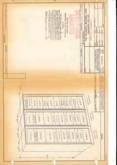 |
| DDR-5A1 |
2xHFR-1 |
HFS-1 |
2xAFC-3 |
2xHFI-1, 2xHNF-1, 2xHFA-1, 2xHAF-1, 1xHSP-2 |
1xHSS-1 |
1xHFP-1 |
HPP-1 |
DVM-4 |
|
| DDR-5B |
HFR-1 |
HFS-1 |
AFC-3 |
HFI-1, HNF-1, HFA-1, HAF-1, HSP-2 |
HSS-1 |
HFP-1 |
HPP-1 |
|
|
| DDR-5B1 |
HFR-1 |
HFS-1 |
AFC-3 |
HFI-1, HNF-1, HFA-1, HSP-2 |
HSS-1 |
HFP-1 |
HPP-1 |
|
|
| DDR-5C |
2xHFR-1 |
2xHFS-1 |
2xAFC-3 |
2xHFI-1, 2xHNF-1, 2xHFA-1, 2xHAF-1, 1xHSP-2 |
2xHSS-1 |
HFP-1 |
HPP-1 |
|
|
| DDR-5CA |
2xHFR-2 |
2xHFS-1 |
2xAFC-3 |
2xHFI-1, 2xHNF-1, 2xHFA-1, 2xHAF-1, 2xHSP-2 |
HSS-1 |
2xHFP-1 |
HPP-1 |
|
|
| DDR-5D |
Unknown |
|
|
|
|
|
|
|
|
| DDR-5E |
2xHFR-1 |
2xHFS-1 |
|
2xSBS-2, 1xHSP-2 |
HSS-2 |
2xHFP-1 |
HPP-2 |
DVC-1 |
|
| DDR-5G |
2xHFR-1 |
2xHFS-1 |
|
2xMSA-1, MCG-1 |
HSS-2 |
HFP-1 |
HPP-2 |
|
|
| DDR-5H |
2xHFR-1A |
HFS-1 |
|
2xMSA-1, MCG-1 |
|
HFP-1, MHPA-1 |
|
|
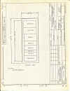 |
| DDR-5J |
2xHFF-1 |
HFS-1 |
|
2xMSA-1, MCG-1 |
|
HFP-1, MFP-1 |
HPP-1 |
|
|
| DDR-5K |
HFR-2 |
HFS-1 |
AFC-3 |
MSA-1, MCG-1 |
HSS-8 |
HFP-1, MFP-1 |
HPP-1 |
|
|
| DDR-5KA |
HFR-2 |
HFS-1 |
AFC-3 |
MSA-1, MCG-1 |
HSS-8 |
HFP-1, MFP-1 |
|
|
|
| DDR-5KB |
HFR-2B |
HFS-2 |
AFC-3 |
MSA-1, MCG-1 |
HSS-8 |
HFP-1, MFP-1 |
HPP-1 |
|
|
| DDR-5KS |
HFR-2B |
HFS-2 |
|
MSA-1, MCG-1 |
HSS-8 |
HFP-1, MFP-1 |
HPP-1 |
220v, 50cps operation |
|
| DDR-5KS1 |
HFR-2B |
HFS-2 |
|
MSA-1, MCG-1 |
HSS-8 |
HFP-1, MFP-1 |
HPP-1 |
220v, 50cps operation |
|
| DDR-5KS1 |
HFR-2B |
HFS-2 |
|
MSA-1, MCG-1 |
SPP-4004 |
HFP-1, MFP-1 |
HPP-1 |
220v, 50cps operation |
|
| DDR-5L |
2xHFR-1A |
HFSR-1 |
2xAFC-3 |
2xMSA-1, 2xMCG-1, 2xHFA-1 |
BSP-6P |
2xHFP-1 |
HPP-1 |
|
|
| DDR-5LS |
2xHFR-2B |
HFS-2 |
|
2xMSA-1, 2xMCG-1 |
BSP-6 |
2xHFP-1 |
HPP-1 |
like 5L, 220V, 50cps op |
|
| DDR-5M |
2xHFR-2 |
2xHFS-1 |
2xAFC-3 |
2xMSA-1, 2xMCG-1 |
2xHSS-6 |
2xHFP-1 |
|
|
|
| DDR-5P |
2xHFR-2 |
HFS-1 |
2xAFC-3 |
2xMSA-1, 2xMCG-1, 2xHFP-1 |
HSS-4 |
|
|
|
|
| DDR-5Q |
HFR-2 |
HFS-1 |
|
MSA-1 |
HSS-5 |
HFP-1 |
|
|
|
| DDR-5R |
HFR-2 |
HFS-1 |
|
MSA-1, MCG-1 |
HSS-4 |
HFP-1 |
|
CFA-1 |
|
| DDR-5S |
HFR-2, HFF |
HFS-1 |
|
HFA, RMXI-2 |
|
HFP-1 |
|
|
|
| DDR-5T |
HFR-2, HFF |
HFS-1 |
|
HFA, RMXI-2 |
|
HFP-1 |
|
|
|
| DDR-5U |
HFR-1A |
HFS-1 |
|
HFI-1, HFA-1, RMXI-2 |
HSS-1 |
HFP-1 |
|
CFA-2 |
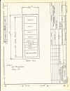 |
| DDR-5V |
HFR-1A |
HFS-1 |
AFC-3 |
MSA-1, MCG-1 |
|
HFP-1 |
|
CFA-1 |
|
| DDR-5Y |
2xHFR-2 |
HFS-1 |
|
2xHFI-1, 2xHFA-1 |
2xBSP-4 |
HFP-1 |
HPP-1 |
2 special filter panels |
|
| DDR-50 |
2xHFR-1 |
HFS-1 |
2xAFC-3 |
2xMSA-1, 2xMCG-1, HSP-2 |
HSS-2 |
2xHFP-1 |
HPP-2 |
|
|
| DDR-51 |
2xHFR-1 |
HFS-1 |
2xAFC-3 |
2xMSA-1, 2xMCG-1 |
HSS-2 |
2xHFP-1 |
HPP-2 |
|
|
| DDR-52 |
HFR-1 |
HFS-1 |
AFC-3 |
MSA-1, MCG-1, HSP-1 |
HSS-2 |
HFP-1 |
HPP-1 |
|
|
| DDR-53 |
2xHFR-1 |
2xHFS-1 |
2xAFC-3 |
2xMSA-1, 2xMCG-1, 2xHSP-1 |
2xHSS-2 |
2xHFP-1 |
2xHPP-1 |
|
|
| DDR-54 |
2xHFR-1 |
2xHFS-1 |
2xAFC-3 |
2xMSA-1, 2xMCG-1, 2xHSP-1 |
2xBSP-2 |
2xHFP-1 |
|
|
|
| DDR-55 |
2xHFR-2 |
HFS-1 |
2xAFC-3 |
2xMSA-1, 2xMCG-1, 1xHFP-1, |
HSS-4 |
HFP-1, MHPA-1 |
|
|
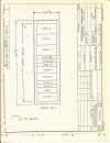 |
| DDR-501 |
HFF-1 |
HFS-1 |
AFC-3 |
MSA-1, MCG-1, HSP-1 |
HSS-2 |
HFP-1 |
|
|
|
| DDR-502 |
2xHFF-1 |
2xHFS-1 |
2xAFC-3 |
2xMSA-1, 2xMCG-1, 2xHSP-1 |
2xHSS-2 |
2xHFP-1 |
|
|
|
| DDR-503 |
2xHFF-1 |
HSF-1 |
2xAFC-3 |
2xHFI-1, 2xHNF-1, 2xHFA-1, 2xHAF-1 |
2xHSS-1 |
2xHFP-1 |
HPP-1 |
DVM-4 |
|
| DDR-505 |
HFR-1A |
HFS-1A |
AFC-3 |
HFI-1, HFA-1, HAF-1, HNF-1, RMX-2 |
BSP-2X |
HFP-1 |
HPP-1 |
|
|
| DDR-551 |
HFR-1 |
HFS-1 |
|
SBS-1 |
HSS |
HFP-1 |
HPP-1 |
|
|
| DDR-551A |
HFR-1 |
HFS-1 |
AFC-3 |
SBS-1 |
HSS |
HFP-1 |
HPP-1 |
|
|
| |
|
|
|
|
|
|
|
|
|
DDR-5
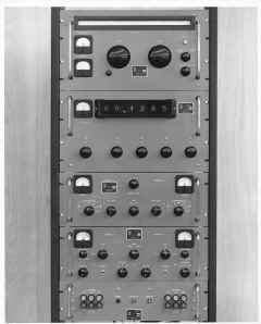
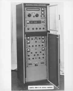
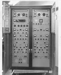
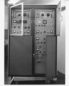
There appears to have been an early version of the DDR-5 receivers called
just "DDR-5". Note the different appearance of the HFR and HFS
units in some of the photos. Indirect evidence from comparing various
photos suggest that these two models were just renamed DDR-5A (dual) and DDR-5B
(single).
 |
 |
 |
 |
| |
621.26-2 This appears to be the
earliest version of the DDR-5 for which there is a photo. Note that the
HFR was quite different in later versions. |
no info on photo |
625.12-2 |
DDR-5A
This is the original dual-diversity version of the receiver. It has
only one HFS Synthesizer, so both halves of the receiver must be tuned to the
same frequency, when the synthesizer is in use, so this is a "spatial
diversity" receiver.
| Left Rack |
Right Rack |
| HFR-1 RF Tuner |
HFR-1 RF Tuner |
| HFS-1 Synthesizer |
DVM-4 Diversity Monitor |
| |
Blank Panel |
| AFC-3 AFC Cntl Unit |
AFC-3 AFC Cntl Unit |
| HSP-2 Audio Switch Panel |
Blank Panel |
| HFI-1 IF Amp |
HFI-1 IF Amp |
| HNF-1 Variable Notch Filter |
HNF-1 Variable Notch Filter |
| HFA-1 Detector and Audio Amp |
HFA-1 Detector and Audio Amp |
| HAF-1 Audio Filter |
HAF-1 Audio Filter |
| HFP-1 Power Supply |
HFP-1 Power Supply |
| HSS-1 Speaker Panel |
HSS-1 Speaker Panel |
| HPP-1 Power Panel |
Blower |
 |
 |
 |
 |
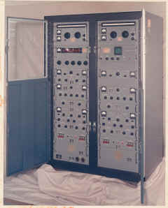
| Un-numbered color photo of DDR-5A |
Also un-numbered, this photo may be of an
early version of the "A"; note the metal rings around the HFR's
left dial, the absence of the HPP-1 power panel at the bottom of the left
rack, and the 2-speaker panel in place of an HSS-1 |
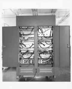
625.12-7 Rear of DDR-5A rack. |
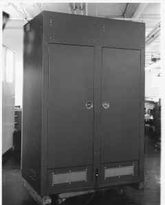
625.12-1 Another shot of the early 'A', with
bottom doors closed. |
 |
 |
|
|
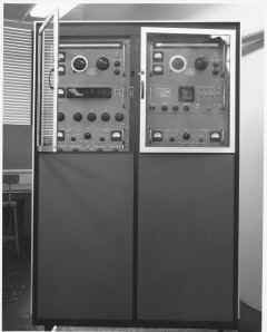
| 625.12-2. Yet another shot of the earl
'A'. |
625.12-6 Early 'A' rear view with doors
shut. |
|
|
| |
|
|
|
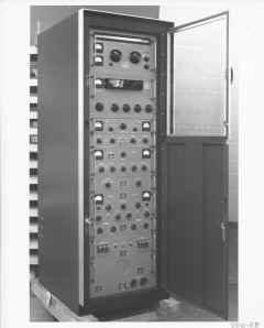
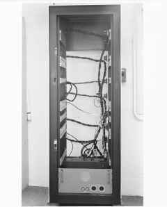
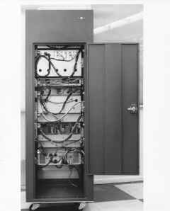
DDR-5B
The "B" model is the single-rack, non-diversity, version of the
"A".
| Configuration |
| HFR-1 RF Tuner |
| HFS-1 Synthesizer |
| AFC-3 AFC Cntl Unit |
| HSP-2 Audio Switch Panel |
| HFI-1 IF Amp |
| HNF-1 Variable Notch Filter |
| HFA-1 Detector and Audio Amp |
| HAF-1 Audio Filter |
| HFP-1 Power Supply |
| HSS-1 Speaker Panel |
| HPP-1 Power Panel |
 |
 |
 |
 |
| 629.14-2 DDR-5B |
6310.11-2 DDR-5 Rack, front |
626.27-4 DDR-5B Rack, rear. |
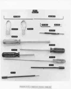
Special tools for DDR-5. |
| |
|
|
|
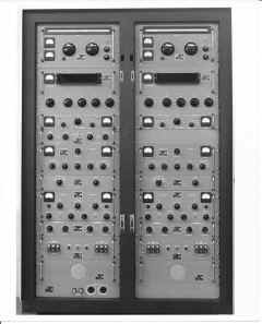
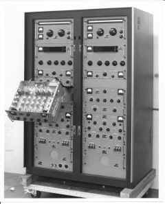
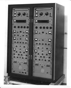
DDR-5C
This version of the receiver is a full frequency/spatial diversity
configuration with two independent synthesizers. Where the "A"
version has only a single HFS to lock both of its HFR's to the same frequency,
the "C' radio has two synthesizers.. essentially two independent
synthesized receivers.
| Left Rack |
Right Rack |
| HFR-1 RF Tuner |
HFR-1 RF Tuner |
| HFS-1 Synthesizer |
HFS-1 Synthesizer |
| AFC-3 AFC Cntl Unit |
AFC-3 AFC Cntl Unit |
| HSP-2 Audio Switch Panel |
Blank Panel |
| HFI-1 IF Amp |
HFI-1 IF Amp |
| HNF-1 Variable Notch Filter |
HNF-1 Variable Notch Filter |
| HFA-1 Detector and Audio Amp |
HFA-1 Detector and Audio Amp |
| HAF-1 Audio Filter |
HAF-1 Audio Filter |
| HFP-1 Power Supply |
HFP-1 Power Supply |
| HSS-1 Speaker Panel |
HSS-1 Speaker Panel |
| HPP-1 Power Panel |
Blower |
 |
 |
 |
|
| 637.9-1 DDR-5C front. |
637.9-3 DDR-5C with HFI swung out. |
637.9-2 DDR-5 overall view. |
|
| |
|
|
|
| |
|
|
|
DDR-5H
This version is a single-rack diversity receiver with 2 sets of 4 independent
sidebands (MSA's).
| Configuration |
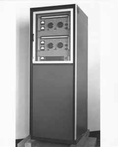 |
643-25-1 |
| HFR-1A RF Tuner |
| HFR-1A RF Tuner |
| HFS-1 Synthesizer |
| MSA-1 Multiple Sideband Adapter |
| MSA-1 Multiple Sideband Adapter |
| MCG-1 Mux Carrier Generator |
| HFP-1 Power Supply |
| MHPA-1 Dual Power Supply |
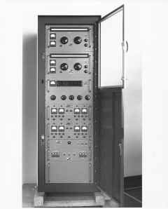
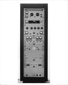
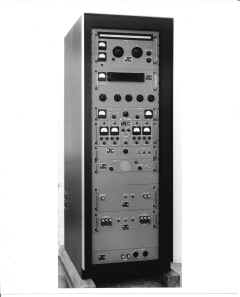
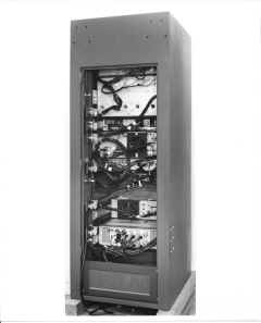
DDR-5K (AN/FRR-74)
This version is a single-rack non-diversity rig, configured to receive 4
independent sidebands.
| Configuration DDR-5K |
Configuration DDR-5KA |
| HFR-2 RF Tuner |
HFR-2 RF Tuner |
| HFS-1 Synthesizer |
HFS-1 Synthesizer |
| AFC-3 AFC Cntl Unit |
AFC-3 AFC Cntl Unit |
| MSA-1 Multiple Sideband Adapter |
MSA-1 Multiple Sideband Adapter |
| MCG-1 Mux Carrier Generator |
MCG-1 Mux Carrier Generator |
| HNF-1 Variable Notch Filter |
HNF-1 Variable Notch Filter |
| HSS-8 Speaker Panel |
HSS-8 Speaker Panel |
| MFP-1 Power Supply |
MFP-1 Power Supply |
| HFP-1 Power Supply |
HFP-1 Power Supply |
| HPP-1 Power Panel |
|
 |
 |
 |
|
| 6511.11-5 DDR-5KC front |
657.8-3 DDR-5K overall view. |
657.8-4 Rear view of DDR-5K rack. |
|
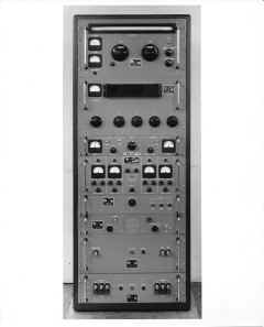 |
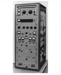 |
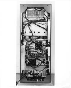 |
|
| 6511.11-5 DDR-5KA front view. |
6511.11-6 DDR-5KA oblique view. |
6511.11-7 DDR-5KA rear view. |
|
| |
|
|
|
DDR-5L
The '5L is the diversity version of the 5K. It can receive two sets of
4 independent sidebands, or using the common synthesizer, one set of 4
independent sidebands in spatial diversity.
| Left Rack |
Right Rack |
| HFR-1A RF Tuner |
HFR-1A RF Tuner |
| HFSR-1 Synthesizer |
Blank Panel |
| AFC-3 AFC Cntl Unit |
AFC-3 AFC Cntl Unit |
| MSA-1 Multiple Sideband Adapter |
MSA-1 Multiple Sideband Adapter |
| MCG-1 Mux Carrier Generator |
MCG-1 Mux Carrier Generator |
| Blank Panel |
BSP-6P Bridging Speaker Panel |
| HFA-1 Detector and Audio Amp |
HFA-1 Detector and Audio Amp |
| HFP-1 Power Supply |
HFP-1 Power Supply |
| Blank Panels |
Blank Panels |
| HPP-1 Power Panel |
Blank Panels |
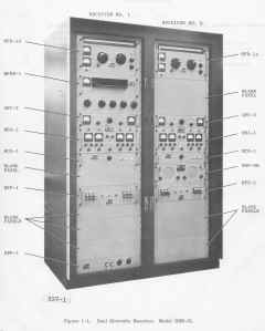 |
 |
 |
|
| Scan of manual page for DDR-5L. |
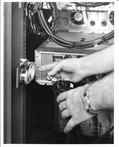
655.24-3 Close-up of cabling. |
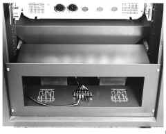
655.26-7 AX-390 in DDR-5L Blower. |
|
| |
|
|
|
DDR-5 Special
This receiver was one of probably many "special"
configurations. This particular one has only an HFR, HFS, HFI, and HFP.
The detector must have been customer supplied, and there was no AFC.
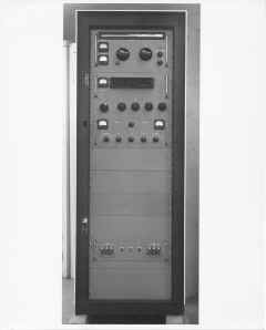
Photo 644.6-6 |
DDR-50
The DDR-50 is a single-rack spatial diversity receiver with 2 HFR's locked to
a single HFS. IF amplifiers, filters, detectors, and audio amps are
implemented in this radio with SBS's.
| Configuration |
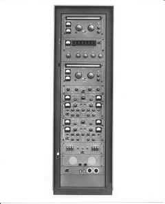
D648.14-2 |
| HFR-1 RF Tuner |
| HFS-1 Synthesizer |
| HFR-1 RF Tuner |
| HSP-2 Audio Switch Panel |
| AFC-2 AFC Cntl Unit |
| SBS-1 Sideband Adapter |
| AFC-2 AFC Cntl Unit |
| SBS-1 Sideband Adapter |
| HFP-1 Power Supply |
| HSS-2 (?) Speaker |
| HPP-1 Power Panel |
DDR-51
The DDR-51, like the '50, is a spatial diversity receiver that also uses a
pair of HFR's with AFC's, sharing a single synthesizer. In this receiver,
however, MSA's and MCG's are used as IF and audio components.
| Configuration |
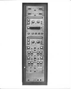
D648.14-1 |
| HFP-1 Power Supply |
| HFP-1 Power Supply |
| HFR-1 RF Tuner |
| HFS-1 Synthesizer |
| HFR-1 RF Tuner |
| AFC-2 AFC Cntl Unit |
| MSA Multiple Sideband Adapter |
| AFC-2 AFC Cntl Unit |
| MSA Multiple Sideband Adapter |
| MCG Mux Carrier Generator |
| MCG Mux Carrier Generator |
| HPP-1 Power Panel |
DDR-52
This version is a non-diversity reciver using an MSA/MCG IF/Detector
assembly.
| Configuration |
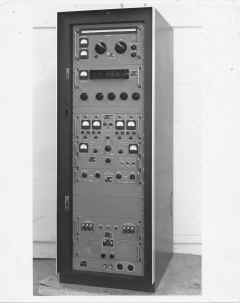
642.8-16 |
| HFR-1 RF Tuner |
| HFS-1 Synthesizer |
| MSA-1 Multiple Sideband Adapter |
| AFC-3 AFC Cntl Unit |
| MCG-1 Mux Carrier Generator |
| HSP Audio Switch Panel |
| HFP-1 Power Supply |
| HSS-2 (?) Speaker |
| HPP-1 Power Panel |
DDR-55
This version appears to be a dual-diversity configuration in a single
cabinet. I don't have photos of the '55.
| Configuration |
| HFR-2 RF Tuner |
| HFR-2 RF Tuner |
| HFS-1 Synthesizer |
| AFC-5 Automatic Freq Controller |
| AFC-5 Automatic Freq Controller |
| HSS-4 Speaker |
| MSA-1 Multiple Sideband Adapter |
| MSA-1 Multiple Sideband Adapter |
| MCG-1 Mux Carrier Generator |
| MCG-1 Mux Carrier Generator |
| HFP-1 Power Supply |
| MHPA-1 Multiple Power Supply |
DDR-501
In this receiver, the manually tuneable HFR is replaced with an HFF, an RF
unit that provides 8 preset, fixed-tuned receive frequencies. The -501
receives 4 independent sidebands in a non-diversity configuration.
| Configuration |
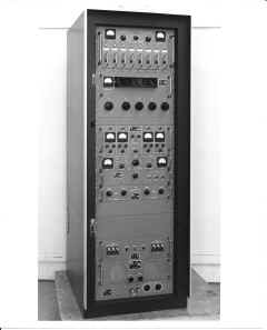
642.8-14 |
| HFF Fixed-tuned RF Unit |
| HFS Synthesizer |
| MSA-1 Multiple Sideband Adapter |
| AFC AFC Control Unit |
| MSG-1 Mux Carrier Generator |
| HSP Audio Switch Panel |
| HFP-1 Power Supply |
| HSS-2 (?) Speaker |
| HPP-1 Power Panel |
DDR-551
The DDR-551 is a non-diversity configuration that uses an SBS dual-channel
IF/detector.
| Configuration |
| HFR RF Tuner |
| HFS Synthesizer |
| SBS-1 Multiple Sideband Adapter |
| HSS-2 (?) Speaker |
| HFP-1 Power Supply |
| HPP-1 Power Panel |
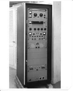 |
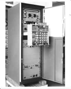 |
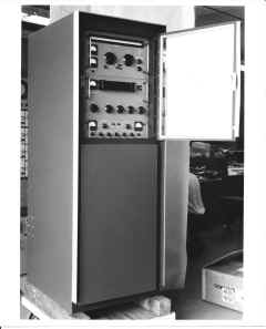 |
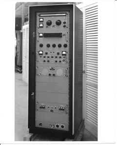 |
| 643.13-2 |
648.19-2 |
648.19-1 |
543.13-3 |
DDR-5 Mystery Radios
In the photo stash there are several photos of DDR-5's that I cannot match up
with any known configurations.
| This version appears to be a single-rack
diversity receiver, without a synthesizer. It has two complete
receivers, each consisting of an HFR, an AFC freq control, and an SBS
multiple sideband adapter. There must be a power supply, or two, but
they must be mounted in the rear of the rack. |
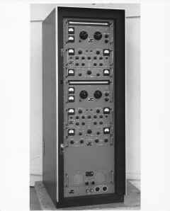
642.8-11 |
| Configuration |
| HFR RF Tuner |
| SBS-1 Multiple Sideband Adapter |
| AFC Automatic Freq Control |
| HFR RF Tuner |
| SBS-1 Multiple Sideband Adapter |
| AFC Automatic Freq Control |
| HSP Audio Switch Panel |
| HSS-8(?) Dual Speaker Panel |
| HPP-1 Power Panel |
| Like the above mystery radio, this one
appears to be a diversity set with no synthesizer, but is uses the MSA/MCG
multiple sideband adpaters instead of the SBS. |
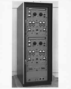
642.8-8 |
| Configuration |
| HFR RF Tuner |
| MSA Multiple Sideband Adapter |
| AFC Automatic Freq Control |
| MCG Multipler Carrier Generator |
| HFR RF Tuner |
| MSA Multiple Sideband Adapter |
| AFC Automatic Freq Control |
| MCG Multipler Carrier Generator |
| HFP Power Supply |
| HPP Power Panel |
| This radio is very similar to the DDR-5B, but
seems to have a different audio switch panel. Examination of the
photo shows that the tags have military designations. |
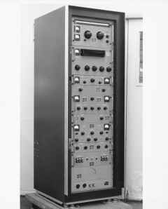 |
| Configuration |
| HFR RF Tuner |
| HFS Synthesizer |
| AFC Automatic Frequency Control |
| (?) Audio Switch Panel, but not HSP |
| HFI IF Amp |
| HFA-1 Detector and Audio Amp |
| HAF-1 Audio Filter |
| HFP-1 Power Supply |
| HSS-? Speaker Panel |
| HPP-1 Power Panel |
| This configuration is similar to the DDR-5K,
but.. not quite the same. It has no MFP power supply. |
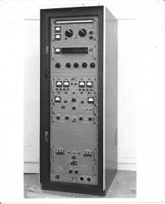 |
| Configuration |
| HFR RF Tuner |
| HFS Synthesizer |
| MSA Multiple Sideband Adapter |
| AFC Automatic Freq Control |
| MCG Multiple Carrier Generator |
| HAF Audio Filter |
| HFP Power Supply |
| HSS-8(?) Speaker Panel |
| HPP Power Panel |
| This radio is very similar to
the DDR-5M. It's a diversity set with 2 tuners, 2 synthesizers, and
2 MSA/MCG sets. It differs from the -5M in its speakers, and in
having a pair of HAF's installed as well |
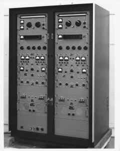
642.8-2 |
| Configuration |
| HFR RF Tuner |
HFR RF Tuner |
| HFS Synthesizer |
HFS Synthesizer |
| MSA Multiple Sideband Adapter |
MSA Multiple Sideband Adapter |
| MCG Multiple Carrier Generator |
MCG Multiple Carrier Generator |
| HAF Audio Filter |
HAF Audio Filter |
| HFP Power Supply |
HFP Power Supply |
| LSP-7 Dual Speaker |
LSP-7 Dual Speaker |
| HPP Power Panel |
|
| This configuration is similar to
both the DDR-5L and DDR-5P with some detailed differences. It
appears to be a dual-diversity radio with MSA/MCG IF/Detector Systems. |
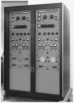
6512.9-8 (Dec 22, 1966) |
|
Configuration |
| HFR RF Tuner |
HFR RF Tuner |
| HFS Synthesizer |
HFS Synthesizer |
| AFC Automatic Freq Control |
AFC Automatic Freq Control |
| MSA Multiple Sideband Adapter |
MSA Multiple Sideband Adapter |
| MCG Multiple Carrier Generator |
MCG Multiple Carrier Generator |
| HFP Power Supply |
HSS-? Dual Speaker |
| HFP Power Supply |
HFP Power Supply |
| |
|
| This version is a
"miniature" single-rack receiver. No markings or info on
the photo |
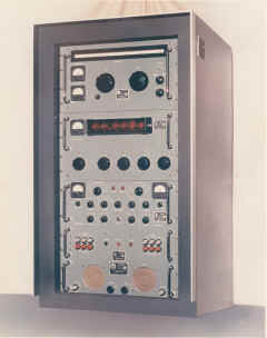 |
| Configuration |
| HFR RF Tuner |
| HFS Synthesizer |
| SBS-1 Multiple Sideband Adapter |
| HFP Power Supply |
| HSS-8(?) Dual Speaker Panel |
Remotely Tuned DDR-5's
In the mid-sixties the Navy and other agencies (notably NASA) developed
requirements for remotely tuned equipment, which lead to TMC's development of
the so-called Technimatic equipment. The DDR-5's were among the first TMC
systems to be provided with remote controls. Early nomenclature wasn't
absolutely consistent, so for example, there is a DDR-5BR (remote version of the
DDR-5B), but later the remotely tuned radios started to be listed as DDRR-5x.
The HFR, HFS, HFA, HFI units of DDR-5 spawned new remotely-tuned versions
HFRR, HFSR, HFAR, HFIR, and so forth. Their appearance from the front
panel is identical to their manually-tuned versions. Viewed from the rear,
however, rows of Ledex rotation actuators is a tip-off that you're looking at an
"xxxR" unit. In addition to the "R" versions, some of
the DDR-5 modules morphed into "A" versions, for example the MSAA,
MCGA and so forth, presumably for "Automatic".
The remote control systems used the following additional units to handle data
reception, decoding, and storage:
| Module |
Picture |
Function |
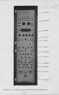
| RTTD |
 |
Data decoder/receiver. This unit
received data from the remote controller via a teletype land line, decoded
the commands, and stored them into the RTMU. RTTD-1 shown. |
| RTMU |
 |
Signal Data Converter-Storer. This unit
received digital commands from the RTTD, stored the commands in a digital
memory, performed decoding functions, and drove the various xxxR units in
the receiver. RTMU-1 shown. |
| LRCB |
 |
Control Terminator, used in the
DDRR-506. This photos is actually of an LRCD-1, but the LRCB is
identical in appearance. |
| |
|
|
The operator end of the remote tuning systems included the ARCx units.
ARCA Automatic Receiver Remote Control System, Tape
 |
 |
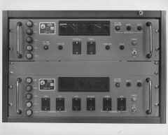 |
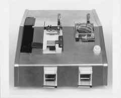 |
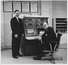
| R6412.2-8. Photo of Ray deP with an
unknown associate at the controls of an ARCA-1 receiver Technimatic remote
control system. This ARCA-1 has 1 RTPA-1 Electronic Programmer, 3
RTIA-1 Channel Indicators, and an RTKY-1 Paper Tape Reader/Punch. |
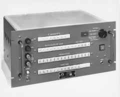
667.13-3. This photo is actually an
RTPH, but the RTPA-1 that is used in the ARCA-1 is almost identical in
appearance. |
654.2-3. The bottom unit in this photo
is an RTIA-1. |
No number. RTKY-1 Paper tape
reader/punch. |
Overview
The following chart lists the various remote-controlled DDR-5 configurations.
| Type |
Tuner |
Synthesizer |
AFC |
IF/Audio/Filter |
Spkr |
Pwr Sup |
AC Pwr Panel |
Remote Cntl |
Other |
Dwg |
| DDR-5BR |
HFRR-2 |
HFSR-1 |
AFCR-3 |
HFIA-1, HFAR-1A, HAFR-1 |
HSS-3 |
HFP-1 |
|
RTMU-1, RTTD-1 |
RGCB-1, AK-101 |
 |
| DDR-5BR1 |
HFRR-2B |
HFS-1 |
AFCR-3 |
HFIA-1, HFAR-1A, HAF-1 |
HSS-3 |
HFP-1 |
|
RTMU-2, RTTD-1 |
RGCB-1, AK-101 |
|
| DDR-5N |
2xHFR-2 |
HFS-1 |
|
2xMSA-1, 1xMCG-1, 2xHFP-1, 1xHSP-2 |
2xBSP-2 |
2xHFP-1 |
|
RTMU-1, RTTD-1 |
4xDVC-1 |
|
| DDR-504 |
HFRR |
HFSR |
|
HFIR, HFAR, HAFR, HFP |
HSS |
PSP-1 |
|
RTMU-1, RTTD-1 |
CFA-1 |
|
| DDR-506 |
8xHFRR-3 |
8xHFSR-1 |
8xAFCR-3 |
8xMSAA-1, 8xMCGA-1 |
|
12xHFP-1 |
|
8xLRCB-1 |
FACA-1 (?) |
|
| DDR-552 |
HFRR-2 |
HFSR-1 |
AFC-3 |
HFIR, HNF, HFAR, HAF |
|
HFP-1 |
|
RTMU-1, RTTK-1, RTPP |
|
|
| DDRR-5B |
HFRR-2 |
HFSR-1 |
AFC-3 |
HFIR-1, HNF-1, HFAR-1, HAF-1 |
HSS-3 |
HFP-1 |
|
RTMU-1, RTTD-1 |
|
 |
| DDRR-5B1 |
HFRR-2 |
HFSR-1 |
AFC-3 |
HFIR-1, HFN-1, HFA-1, HAFR-1, HSP-2 |
HSS-6 |
HFP-1 |
|
RTMU-1, RTTD-1 |
|
|
| DDRR-5C |
2xHFRR-2 |
2xHFSR-1 |
2xAFC-3 |
2xHFIR-1, 2xHNF-1, 2xHFAR-1, 2xHAF-1 |
2xHSS-3 |
2xHFP-1 |
|
2xRTMU-1, 2xRTTD-1 |
|
|
| DDRR-5K |
HFRR-2 |
HFSR-1 |
AFC-3 |
MSA-1, MCG-1 |
1x(?) |
HFP-1 |
|
RTMU-1, RTTD-1 |
|
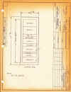 |
| DDRR-5L |
2xHFRR-2 |
HFSR-1 |
2xAFC-3 |
2xMSA-1, 2xMCG-1 |
1x(?) |
2xHFP-1 |
|
RTMU-1, RTTD-1 |
RSTA-1 (?) |
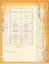 |
| DDRR-5M |
2xHFRR-2 |
2xHFSR-1 |
2xAFC-3 |
2xMSA-1, 2xMCG-1 |
BSP-6B |
2xHFP-1 |
|
2xRTMU-1, 2xRTTD-1 |
|
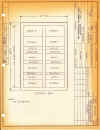 |
| DDRR-5N |
2xHFRR-2 |
HFSR-1 |
|
2xMSA-1, 1xMCG-1, 1xHSP-2 |
2xBSP-2 |
2xHFP-1 |
|
RTMU-1, RTTD-1 |
4xDVC-1 |
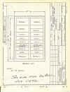 |
| DDRR-5P |
2xHFRR-2 |
2xHFSR-1 |
2xAFC-3 |
2xMSA-1, 2xMCG-1 |
1x(?) |
2xHFP-1 |
|
RTMU-1, RTTD-1 |
|
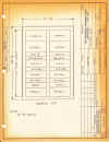 |
| DDRR-5Q |
HFRR-2 |
HFSR-1 |
|
MSA-1 |
HSSR-5 |
HFP-1 |
|
RTMU-1, RTTD-1 |
|
|
| DDRR-5R |
HFRR-2 |
HFSR-1 |
|
MSA-1, MCGR-1 |
HSS-4 |
HFP-1 |
|
RTMU-1, RTTD-1 |
CFA-1 |
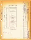 |
| DDRR-5S |
HFRR-2 |
HFSR-1 |
|
SBS-1, RMXI-2 |
HSS-4 |
HFP-1 |
|
RTMU-1, RTTD-1 |
CFA-1 |
|
| DDRR-5T |
HFRR-2 |
HFSR-1 |
|
HFI-1, HFA-1, RMXI-2 |
|
HFP-1 |
|
RTMU-1, RTTD-1 |
|
|
| DDRR-5W |
HFRR-( ) |
HFSR-1 |
AFC-3 |
HFIR-2, HFA-1 |
|
HFP-1 |
HPP-1 |
RTMU-3, RTTD-3 |
|
|
| |
|
|
|
|
|
|
|
|
|
|
| |
|
|
|
|
|
|
|
|
|
|
DDRR-5B
This version is the remotely tuned version of the single-rack, non-diversity
DDR-5B. This receiver appears to have been configured in several alternate
ways, including the DDRR-5B1. There were early versions of this receiver,
again with slightly different configurations, designated the DDR-5BR and
DDR-5BR1..
| Configuration DDRR-5B |
Configuration DDRR-5B1 |
Configuration DDR-5BR |
Configuration DDR-5BR1 |
| RTTD-1 Data Decoder/Receiver |
RTTD-1 Data Decoder/Receiver |
RTTD-1 Data Decoder/Receiver |
RTTD-1 Data Decoder/Receiver |
| HFRR-2 RF Tuner |
HFRR-2 RF Tuner |
HFRR-2 RF Tuner |
HFRR-2B RF Tuner |
| HFSR-1 Synthesizer |
HFSR-1 Synthesizer |
HFSR-1 Synthesizer |
HFS-1 Synthesizer |
| AFC-3 Automatic Freq Control |
AFC-3 Automatic Freq Control |
AFCR-3 Automatic Freq Control |
AFCR-3 Automatic Freq Control (remote
version!) |
| HSS-6 Speaker |
HSS-6 Speaker |
HSS-3 Speaker |
HSS-3 Speaker |
| HFIR-1 IF Amp |
HSP-2 Audio Switch Panel |
HFIA-1 IF Amp |
HFIA-1 IF Amp |
| HFA-1 Detector & Audio Amp |
HFIR-1 IF Amp |
HFAR-1A Detector & Audio Amp |
HFAR-1A Detector & Audio Amp |
| HAFR-1 Audio Filter |
HFN-1 Variable Notch Filter |
HAFR-1 Audio Filter |
HAF-1 Audio Filter (non-remote) |
| HFN-1 Variable Notch Filter |
HFA-1 Detector & Audio Amp |
RGCB-1 Remote Gain Control |
RGCB-1 Remote Gain Control |
| HFP-1 Power Supply |
HAFR-1 Audio Filter |
HFP-1 Power Supply |
HFP-1 Power Supply |
| RTMU-1 Data Converter/Storer |
HFP-1 Power Supply |
RTMU-2 Data Converter/Storer |
RTMU-2 Data Converter/Storer |
| |
RTMU-1 Data Converter/Storer |
AK-101 Isolation Keyer |
AK-101 Isolation Keyer |
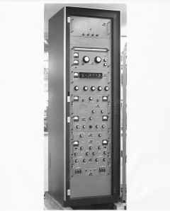 |
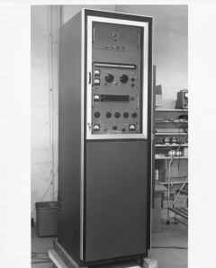 |
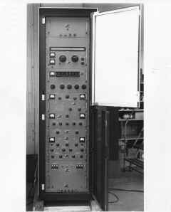 |
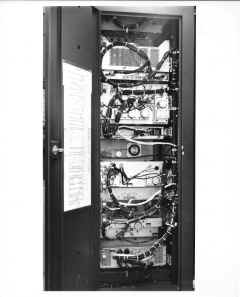 |
| 646.10-3. DDRR-5B described on back of
photo as "incomplete". There appears to be no RTMU at the
bottom. |
6411.2-3 DDRR-5B with rack door closed. |
6411.2-1 DDRR-5B with rack doors open. |
652.18-11. DDRR-5B rear view. |
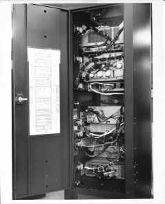 |
 |
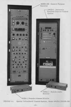 |
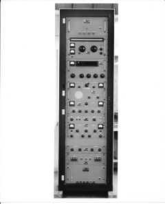 |
| 652.18-11. DDRR-5B from left rear. |
DDRR-5B1 front view. |
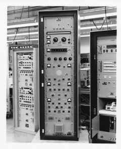
DDRR-5B1 with ARCD-1 remote controller. |
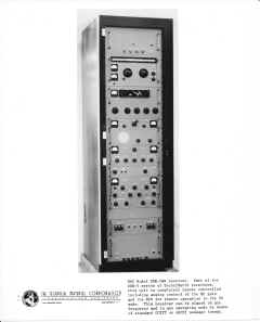
662.18-7. DDR-5BR1 front view. |
 |
 |
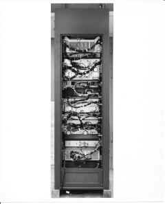 |
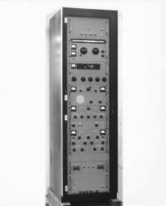 |
| DDRR-5B1 shown on the production line, with
an ARCD-1 at the right, and a DDR-10 of some flavor on the left. |
DDR-5BR1 annotated photo. |
662.18-10. DDR-5BR1 rear view. |
DDR-5BR overall view. |
| |
|
|
|
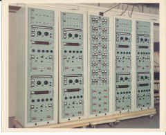
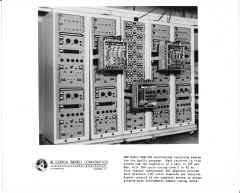
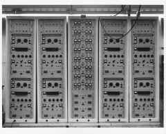
DDRR-506
This monster (referred to sometimes as the DDR-506) was built for NASA and
deployed on the tracking ships used for the Apollo program. The radios
were a backup system to be used in case the satellite-based data link
failed. Evidently the satellite system failed during at least one of the
moon missions, and this receiver was used to receive, download, and then uplink
the lunar injection burn data for the spacecraft. Quite an accomplishment
for an HF link!
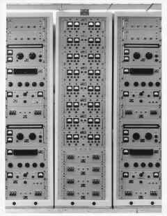
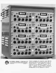
The radio consists of 8 separate receivers, all remotely controllable.
The NASA receivers, and their parts, are easily identifiable, as they are
painted a bilious green color, rather than the usual "TMC gray".
| Configuration |
| LRCB-1 Control Terminator |
LRCB-1 Control Terminator |
MSAA-1 Multiple Sideband Adapter |
LRCB-1 Control Terminator |
LRCB-1 Control Terminator |
| LRCB-1 Control Terminator |
LRCB-1 Control Terminator |
MSAA-1 Multiple Sideband Adapter |
LRCB-1 Control Terminator |
LRCB-1 Control Terminator |
| HFRR-3 RF Tuner |
HFRR-3 RF Tuner |
MSAA-1 Multiple Sideband Adapter |
HFRR-3 RF Tuner |
HFRR-3 RF Tuner |
| HFSR-1 Synthesizer |
HFSR-1 Synthesizer |
MSAA-1 Multiple Sideband Adapter |
HFSR-1 Synthesizer |
HFSR-1 Synthesizer |
| AFCR-3 Automatic Freq Control |
AFCR-3 Automatic Freq Control |
MSAA-1 Multiple Sideband Adapter |
AFCR-3 Automatic Freq Control |
AFCR-3 Automatic Freq Control |
| MCGA-1 Multiple Carrier Generator |
MCGA-1 Multiple Carrier Generator |
MSAA-1 Multiple Sideband Adapter |
MCGA-1 Multiple Carrier Generator |
MCGA-1 Multiple Carrier Generator |
| HFP-1 Power Supply |
HFP-1 Power Supply |
MSAA-1 Multiple Sideband Adapter |
HFP-1 Power Supply |
HFP-1 Power Supply |
| HFRR-3 RF Tuner |
HFRR-3 RF Tuner |
MSAA-1 Multiple Sideband Adapter |
HFRR-3 RF Tuner |
HFRR-3 RF Tuner |
| HFSR-1 Synthesizer |
HFSR-1 Synthesizer |
FACA-1 (not sure about this one) |
HFSR-1 Synthesizer |
HFSR-1 Synthesizer |
| AFCR-3 Automatic Freq Control |
AFCR-3 Automatic Freq Control |
HFP-1 Power Supply |
AFCR-3 Automatic Freq Control |
AFCR-3 Automatic Freq Control |
| MCGA-1 Multiple Carrier Generator |
MCGA-1 Multiple Carrier Generator |
HFP-1 Power Supply |
MCGA-1 Multiple Carrier Generator |
MCGA-1 Multiple Carrier Generator |
| HFP-1 Power Supply |
HFP-1 Power Supply |
HFP-1 Power Supply |
HFP-1 Power Supply |
HFP-1 Power Supply |
| |
|
HFP-1 Power Supply |
|
|
 |
 |
 |
 |
| Color shot showing the front panel of the
5-rack DDRR-506 (also sometimes referred to as the DDR-506). |
Closeup of the '506 showing mainly the center
rack with its array of 8 MSAA-1's. |
Annotated photo of the '506. |
Front view of the '506. |
 |
 |
|
|
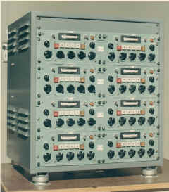
| Operator's console for the DDR(R)-506,
consisting mainly of 8 LRCC-1's. |
Color shot of the LRCC-1's. |
|
|


